Hardware
This section describes the hardware side of the UFSC ground station and details the main peripherals that will be used in this project. Most of the components described here are represented in the block diagram.
Antennas
There are four antennas in the ground station: One for VHF, two for the UHF band, and one for the S-Band. The main characteristics of these antennas can be seen in Table 3.
Characteristic |
VHF Antenna |
UHF Antenna |
UHF Antenna |
S-Band Antenna |
|---|---|---|---|---|
Brand |
M² |
M² |
M² |
TBD |
Model |
2MCP14 |
403CP20 |
466CP42 |
TBD |
Type |
Yagi |
Yagi |
Yagi |
TBD |
Number of elements |
14 |
10 |
20 |
TBD |
Frequency range |
143-148 MHz |
398-408 MHz |
462-470 MHz |
TBD |
Gain |
12.34 dBi |
14 dBi |
19 dBi |
TBD |
Power rating |
1500 W |
1500 W |
600 W |
TBD |
Boom length |
3.2 m |
1.95 m |
5.54 m |
TBD |
Longest element |
1.02 m |
0.381 m |
0.297 m |
TBD |
Weight |
2.72 kg |
2.72 kg |
5.90 kg |
TBD |
More information about the VHF and UHF antennas can be found in [3], [4] and [2] respectively.
Surge Protector
To protect the ground station electronics of possible atmospheric discharges in the outside components, two surge protectors will be used (one for each antenna). The gas surge protectors safely discharge/deflect up to 5000 A of peak current to earth without causing damage to an independent ground. This kind of device is installed near the antennas, in cascade with the RF cables.
For this project the model MFJ-270N will be used, and a picture of it can be seen in Fig. 2.
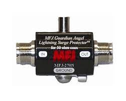
Fig. 2 MFJ-270N surge protector.
Rotator
All antennas track the satellite through a two-axis rotator (azimuth and elevation). The used model is the Hy-Gain RAS-2, which is a heavy-duty antenna rotator designed for medium to large HF and VHF/UHF antennas. It features a robust construction with a 1,000 lb (454 kg) thrust bearing and 200 lb (91 kg) continuous wind load rating, making it suitable for demanding installations. The rotator uses a dual-drum cable system for precise 360-degree rotation and includes automatic braking to prevent unwanted movement.
A picture of this rotator can be seen in Fig. 3, and the main characteristics can be found in Table 4.
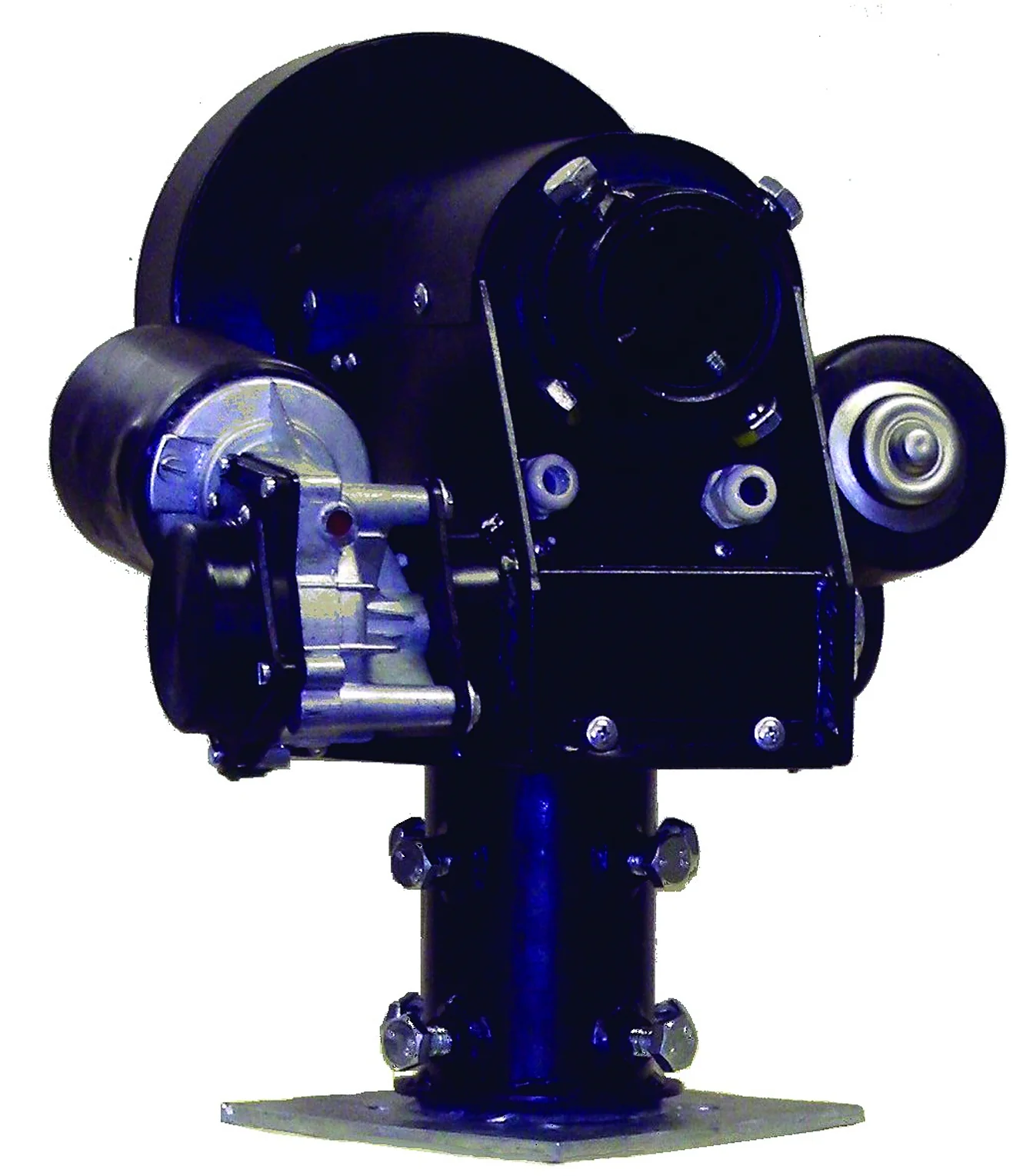
Fig. 3 Hy-Gain RAS-2 rotator and controller.
Characteristic |
Value |
|---|---|
Brand |
Hy-Gain |
Model |
RAS-2 |
Voltage requirement |
12-24 VDC |
Current consumption |
3-5 A |
Motor voltage |
13.8-24 VDC |
Rotation time (elevation, 180°) |
80 sec (12 V), 40 sec (24 V) |
Rotation time (azimuth, 360°) |
120 sec (12 V), 60 sec (24 V) |
Rotation torque (elevation) |
58 kg·m |
Rotation torque (azimuth) |
58 kg·m |
Braking torque (elevation and azimuth) |
276 kg·m |
Vertical load |
318 kg |
Pointing accuracy |
1 degree |
Wind surface area |
2.8 m2 |
Weight |
20 kg |
More information about the ground station rotator can be found in [7].
Amplifiers
Power Amplifiers (VHF/UHF)
A picture of the power amplifier can be seen in Fig. 4, and the main characteristics are available in Table 5.
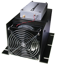
Fig. 4 Mini-Circuits ZHL-50W-52-S+ power amplifier.
Characteristic |
Value |
|---|---|
Brand |
Mini-Circuits |
Model |
ZHL-50W-52-S+ |
Frequency range |
50-500 MHz |
Gain |
47-52 dB |
Noise figure |
4.5-7.0 dB |
DC supply voltage |
24-25 V |
Max. supply current |
9.3 A |
More information about this PA can be found in [5].
Power Amplifiers (S-Band)
Note
TODO
Low-Noise Amplifier (VHF/UHF)
For the LNA of the VHF/UHF bands, the Mini-Circuits ZFL-500LN+ model is being used. It operates over a wide frequency range of 0.1 to 500 MHz, making it suitable for communications, test equipment, and signal boosting in weak-signal environments. A picture of this device is available in Fig. 5, the main specs can be seen in Table 6.
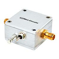
Fig. 5 Mini-Circuits ZFL-500LN+ LNA.
Characteristic |
Value |
|---|---|
Brand |
Mini-Circuits |
Model |
ZFL-500LN+ |
Frequency range |
0.1 to 500 MHz |
Noise figure |
2.9 dB |
Gain |
24 dB (Min.) |
Maximum output power |
5 dBm |
Input voltage |
15 V |
Current consumption |
15 mA (Nominal) |
More information about this LNA can be found in [6].
RF Controller
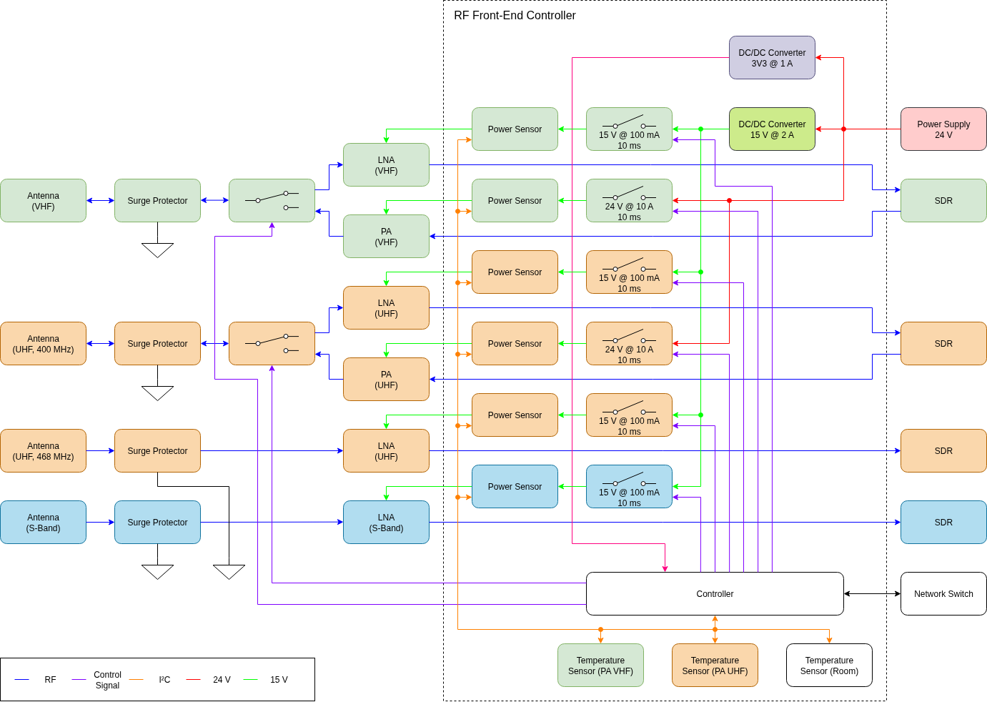
Fig. 6 Block diagram of the RF front-end controller.
Note
TODO
Software Defined Radio
As presented in Fig. 1, the ground segment also has three SDR transceivers. The deployed model is the USRP N210 from Ettus Research [1], a high-performance, networked software-defined radio platform. Unlike single-board designs with integrated RFICs (e.g., AD9361), the N210 features a modular architecture with:
Frequency coverage: DC to 6 GHz (via interchangeable daughterboards like SBX/WBX).
FPGA processing: Xilinx Spartan 3A-DSP 1800 for customizable signal processing.
Host connectivity: Gigabit Ethernet (1 GbE) for high-throughput streaming.
Synchronization: 10 MHz reference clock and PPS input for multi-unit coordination.
The platform supports the USRP Hardware Driver (UHD), enabling seamless integration with GNURadio and other SDR frameworks. A picture of the USRP N210 SDR (with enclosure) can be seen in Fig. 7.
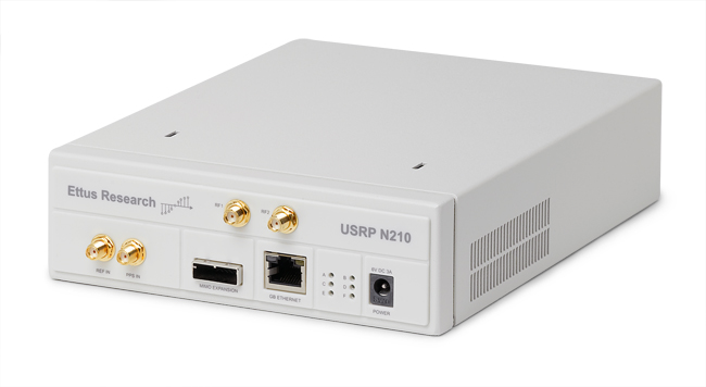
Fig. 7 Ettus USRP N210 SDR.
The Table 7 lists the key hardware specifications of the USRP N210 SDR.
Category |
Specification |
|---|---|
RF Performance |
|
Frequency Range |
DC – 6 GHz (with compatible daughterboard) |
Maximum Bandwidth |
50 MHz (25 MHz usable in practice) |
ADC Resolution |
14-bit |
DAC Resolution |
16-bit |
Processing & Connectivity |
|
FPGA |
Xilinx Spartan 3A-DSP 1800 |
Host Interface |
Gigabit Ethernet (1 GbE) |
Sample Rate (Complex) |
Up to 100 MS/s |
Synchronization |
|
Reference Clock Input |
10 MHz (external) |
PPS Input |
Yes (for timing synchronization) |
Expansion & Power |
|
Daughterboard Slots |
2 (supports SBX, WBX, etc.) |
MIMO Capability |
Yes (2x2 with secondary USRP) |
Power Supply |
6–12 V DC (9–12 V recommended) |