Assembly, Integration and Test
The following activities refer to the Flight Model, so after the execution of this AIT the CubeSat will not suffer any modification in its hardware, software, and firmware. The only acceptable interference is the recharge of batteries, which is made through an external umbilical cable.
In Fig. 61 there is a general view of the sequential steps to the entire AIT campaign, where I refers to integration activities and T is used for testing activities.
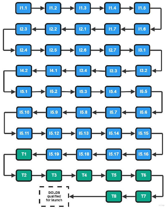
Fig. 61 Sequence of activities of AIT plan.
Assembly Instructions
Each task in the Integration segment of the AIT campaign is listed in Table 27 together with a label for the block, name and section with further details.
Block |
Name |
Section |
|---|---|---|
I1.2 |
I1.2: To pre-mount battery+case and EPS |
I1 |
I1.3 |
I1.3: I1.2+Bottom structure |
I1 |
I1.4 |
I1.4: I1.3+Primary OBDH |
I1 |
I1.5 |
I1.5: I1.4+Radiation Monitor |
I1 |
I1.6 |
I1.6: I1.5+Interface Module |
I1 |
I1.7 |
I1.7: I1.6+Top structure |
I1 |
I2.1 |
I2.1: To pre-mount upper (U) modules |
I2 |
I2.2 |
I2.2: Interface Module+Bottom structure |
I2 |
I2.3 |
I2.3: I2.2+Redudant EDC |
I2 |
I2.4 |
I2.4: I2.3+Primary EDC |
I2 |
I2.5 |
I2.5: I2.4+Radiation instrument |
I2 |
I2.6 |
I2.6: I2.5+TT&C |
I2 |
I2.7 |
I2.7: I2.6+Top structure |
I2 |
I3.1 |
I3.1: Debug interface (-X and +X)+Lateral structure |
I3 |
I3.2 |
I3.2: I3.1+ADCS+Lateral structure |
I3 |
I3.3 |
I3.3: I1.7+ADCS |
I3 |
I3.4 |
I3.4: I2.7+Magnet+upper(U) top structure |
I3 |
I4.1 |
I4.1: I1.7+I2.7+I3.5 |
I4 |
I1.1 |
I1.1: To pre-mount lower (U) modules |
I4 |
I4.2 |
I4.2: I4.1 and I4.2+Debug interface (-Y and +Y)+Lateral structure |
I4 |
I5.1 |
I5.1: I4.2+Shield (-Z) |
I5 |
I5.2 |
I5.2: I5.1+Shield (Z0;X0) |
I5 |
I5.3 |
I5.3: I5.2+Shield (Z0;X1) |
I5 |
I5.4 |
I5.4: I5.3+Shield (Z0;Y0) |
I5 |
I5.5 |
I5.5: I5.4+Shield (Z0;Y1) |
I5 |
I5.6 |
I5.6: I5.5+Shield (Z1;X0) |
I5 |
I5.7 |
I5.7: I5.6+Shield (Z1;X1) |
I5 |
I5.8 |
I5.8: I5.7+Shield (Z1;Y0) |
I5 |
I5.9 |
I5.9: I5.8+Shield (Z1;Y1) |
I5 |
I5.10 |
I5.10: I5.9+Antenna+SP(+Z) |
I5 |
I5.11 |
I5.11: I5.10+SP (-Z) |
I5 |
I5.12 |
I5.12: I5.11+SP (Z0;X0) |
I5 |
I5.13 |
I5.13: I5.12+SP (Z0;X1) |
I5 |
I5.14 |
I5.14: I5.13+SP (Z0;Y0) |
I5 |
I5.15 |
I5.15: I5.14+SP (Z0;Y1) |
I5 |
I5.16 |
I5.16: I5.15+SP (Z1;X0) |
I5 |
I5.17 |
I5.17: I5.16+SP (Z1;X1) |
I5 |
I5.18 |
I5.18: I5.17+SP (Z1;Y0) |
I5 |
I5.19 |
I5.19: I5.18+SP (Z1;Y1) |
I5 |
Environmental Testing
After the integration, the tests that will be executed in the AIT campaign to qualify GOLDS-UFSC for launch are in Table 28. Each of these tests receives the letter T and a number for identification.
Block |
Name |
Criteria |
|---|---|---|
T1 |
Dimensions |
Dimensions of 100.0 × 100.0 × 227.0 mm ±0.1 mm in the X, Y, and Z axis |
T2 |
Fit check |
Absence of interference and a smooth sliding through the deployer |
T3 |
Mass |
Total CubeSat mass below or equal to 4.00 kg |
T4 |
Center of gravity |
It must be within ±2.0 cm from the geometric center on the X-Axis and Y-Axis, and less than ±4.5 cm in Z-axis |
T5 |
Vibration |
To be defined by the launch vehicle |
T6 |
Thermal cycling |
To be defined by the launch vehicle |
T7 |
Thermal Vacuum Bake-out |
To be defined by the launch vehicle |
T8 |
EMC testing |
To be defined by the launch vehicle |
The sequence of these tests is summarized in Fig. 62.
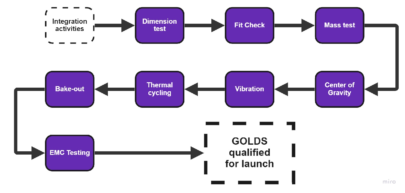
Fig. 62 Test sequence for GOLDS-UFSC.
In the following sections, these tests are described.
Dimensions
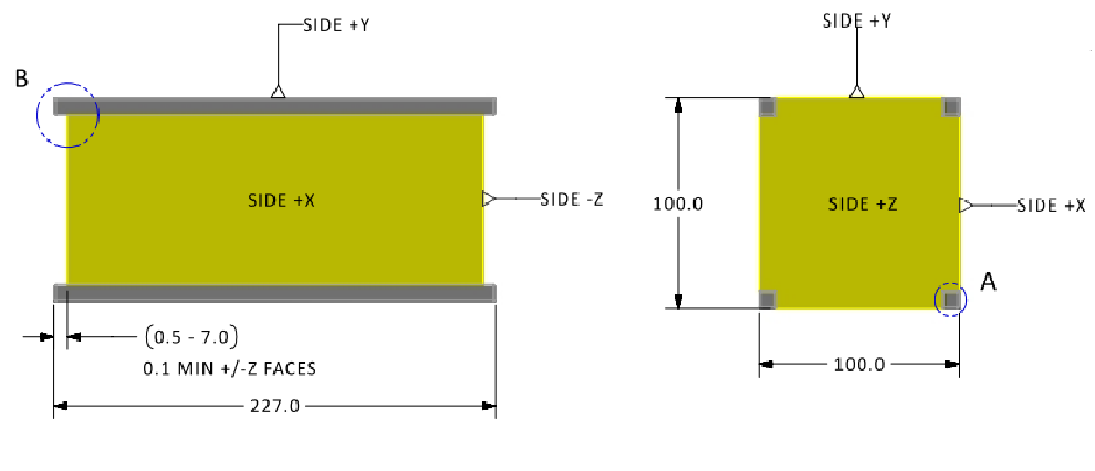
This test checks the main external dimensions of GOLDS-UFSC and aims to prove that its dimensions are appropriate for integration in a standard 2U CubeSat deployer. The dimensional test is validated by measuring with a caliper or micrometer the main external dimensions of GOLDS-UFSC, according to Fig. 63. The tolerance is ±0.1 mm in the X, Y, and Z axis. Any measurement out of this range means the CubeSat is not ready for launch.
Fit check
To assure a proper integration and deployment of the CubeSat, a similar 2U deployer used by the launch is fundamental to verify any additional mechanical interference between these interfaces, as illustrated in Fig. 64. A smooth sliding through the deployer, the absence of interference, and proper pressing of kill-switches are required for qualification.
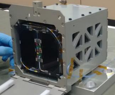
Fig. 64 FloripaSat-1 fit check.
Therefore, this activity lacks a better definition until the launch vehicle and its mandatory deployer are confirmed.
Mass
This test checks the satellite’s total mass (without RBF tag), which must be less than 4.00 kg for a 2U CubeSat [40]. The verification is made with a precision balance. Fig. 65 exemplifies this process with the CubeSat 1U FloripaSat-1.
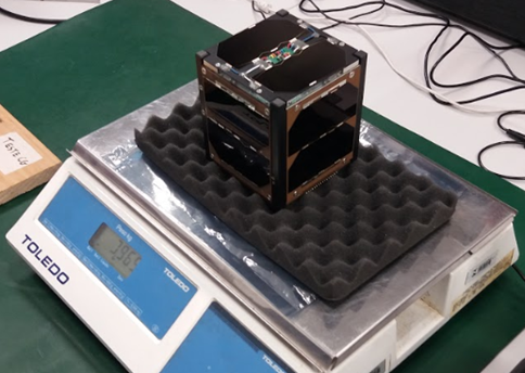
Fig. 65 Mass verification of FloripaSat-1.
Center of Gravity
This test checks the Center of Gravity (CG) of the satellite and proves if it is within the acceptable range. The CG must be within ±2.0 cm from the geometric center on the X-Axis and Y-Axis, and within ±4.5 cm from the geometric center on the Z-Axis [40]. To perform this test, a simple test bench with parallel bars is used. To perform the test, the bars are 4.0 cm apart (to test in the X and Y-axis) or 9.0 cm apart (to test the Z-axis), the geometric center of CubeSat is positioned above them, right between the bars. The CubeSat is not going to tip if the CG is within the range. This strategy does not measure the location of CG; however, it does prove that the satellite follows the requirement.
This test was already validated with FloripaSat-1, as illustrated in Fig. 66, where a caliper is used to verify that the distance between the bars are 4.0 cm.
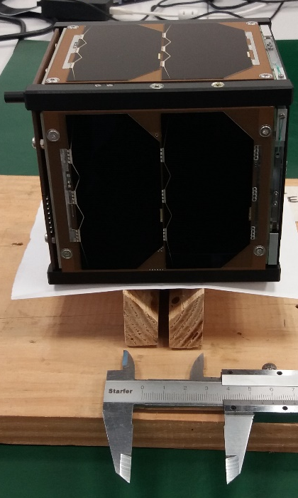
Fig. 66 Center of gravity of FloripaSat-1 within ±2.0 cm from the geometric center.
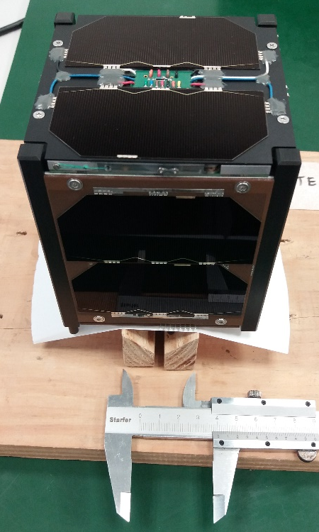
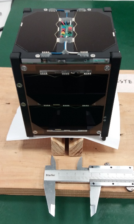
\(X\) axis.
\(Y\) axis.
\(Z\) axis.
Vibration
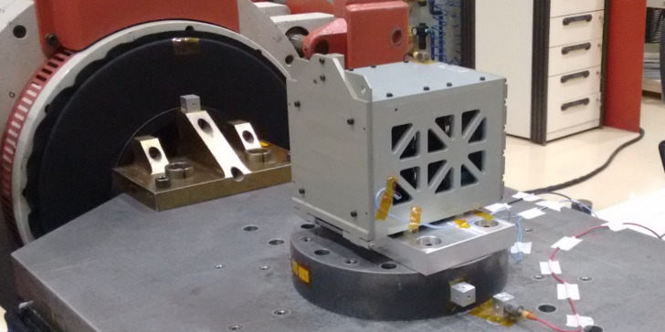
During the launch phase, a significant level of vibration is expected, which can cause failures in the CubeSat. To determine if the CubeSat supports those loads, vibration test are performed. To measure and control the acceleration profile during the dynamic tests, accelerometers are positioned on three external surfaces of the satellite, one on each axis, over areas without solar cells to avoid any damage to them, as illustrated for the case of FloripaSat-1 in Fig. 67. After that, the satellite is integrated into a 2U test deployer, and then the deployer is fixed on a shaker, as seen in Fig. 67.
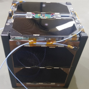
Fig. 67 Vibration test.
Position of the accelerometers.
Shaker.
The CubeSat is tested entirely off, with RBF pin removed, but with the Kill-Switches pressed by the 2U Test POD, simulating the normal launching condition. The envelope of vibration is determined by the launch vehicle, therefore, this activity lacks a better definition until the launch vehicle is confirmed.
Nevertheless, this test is usually executed for most of the CubeSat missions, so a preliminary set of vibration tests is anticipated in Fig. 68. This process will be followed until further information from the launch vehicle is provided.
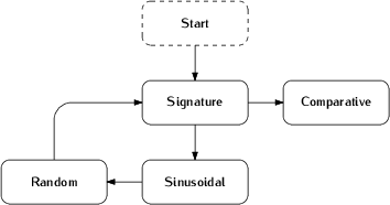
Fig. 68 Sequence of dynamic tests.
A signature testing should be conducted before and after the tests (sinusoidal and random vibration), in order to identify the presence of significant variations in the dynamic response of the CubeSat, a condition that may represent internal mechanical failures that are non-visible from outside.
For the signature task, Table 29 presents the specifications.
Name |
Parameter |
|---|---|
Test method |
Sinusoidal sweep testing |
Frequency range |
5 - 2000 Hz |
Vibration level |
0.25 g |
Sweep rate |
2 octaves per minute |
Number of sweeps |
1 (5 - 2000 Hz) |
Test axes |
3 (\(X\), \(Y\), \(Z\)) |
Sinusoidal vibration test
The sinusoidal vibration test should simulate low-frequency quasi-harmonic excitation of the launch in the order of 5 to 100 Hz. The level of sine sweeping vibration test is listed in Fig. 69 and Table 30.
Acceptance: Frequency Range (Hz) |
Acceptance: Vibration Amplitude |
Qualification: Frequency Range (Hz) |
Qualification: Vibration Amplitude |
|---|---|---|---|
5–8 |
2.33mm(0-p) |
5–8 |
3.49mm(0-p) |
8–100 |
0.6g |
8–100 |
0.9g |
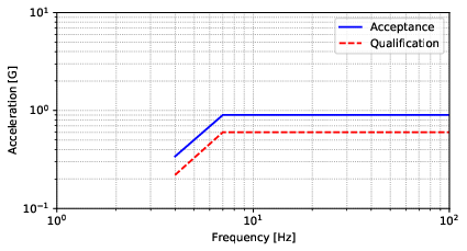
Fig. 69 Sinusoidal sweeping vibration curve.
The sweeping rates of the acceptance test and qualification tests are 4oct/min and 2oct/min, respectively. The test directions are along three orthogonal axes, and the levels along the three directions are the same. Input amplitude errors do not exceed \(\pm 10\)% while frequency error is \(\pm2\)% when frequency \(>\) 25 Hz or \(\pm0.5\) Hz when frequency \(\leq\) 25 Hz.
Random vibration
This test follows the NASA-STD-7001B standard. This test profile is specified in Fig. 70 and illustrated in Fig. 71. The random vibration is performed by 2 minutes, along each of three orthogonal axes.
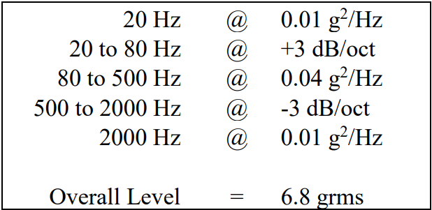
Fig. 70 Component Minimum Workmanship Random Vibration Test Levels.
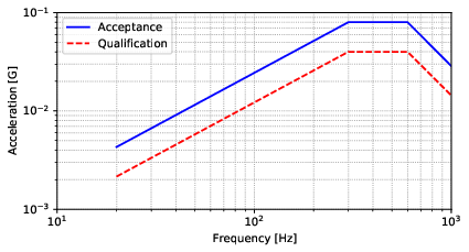
Fig. 71 Random vibration test.
Thermal Cycling
For the thermal tests, thermocouples are attached to different points on the surface of the satellite, including over the solar panels and structure. For example, Fig. 72 shows FloripaSat-1 ready for thermal tests. This test may ruled by the launch vehicle requirements, but until there is no further information about it, the parameters of the tests are summarized in Table 31.
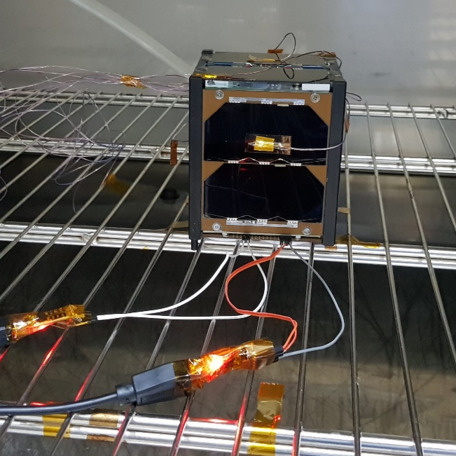
Fig. 72 FloripaSat-1 during the thermal cycling (with thermocouples).
Parameter |
Value |
|---|---|
Number of cycles |
6 |
Minimum temperature |
\(T_{min}=-15 ^\circ\)C |
Maximum temperature |
\(T_{max}=+50 ^\circ\)C |
Duration in \(T_{min}\) |
30 min |
Duration in \(T_{max}\) |
60 min |
Heating rate |
5.5 °C/min |
Cooling rate |
3.5°C/min |
Stabilization criteria |
1°C/10 min |
Bake Out
Here the CubeSat is exposed to a high temperature in a high vacuum environment during a determined time to stimulate their outgassing to fulfill a requirement established to launch. The Bake-out test requirements usually come from the launch provider, but in the absence of this information, the plan is summarized in Table 32.
Parameter |
Value |
|---|---|
Part 1 |
|
Pressure |
<1\(\times 10^{-4}\) mbar |
Temperature |
23 °C |
Duration |
12 hours |
Part 2 |
|
Pressure |
<1\(\times 10^{-4}\) mbar |
Temperature |
60 °C |
Duration |
6 hours |
EMC Testing
EMC: Radiation Emission(RE)
For EMC Radiation Emission test, refer to ECSS-E-ST-20-07C clause 5.4.6. The levels can be found at ECSS-E-ST-20-07C Annex A. The number of applications shall be one.
EMC: Conducted Emission (CE)
For EMC Conducted Emission test, refer to ECSS-E-ST-20-07C clause 5.4.2 The levels can be found at ECSS-E-ST-20-07C Annex A. The number of applications shall be one.
EMC: Radiation Susceptibility (RS)
For EMC Radiation Susceptibility test, refer to ECSS-E-ST-20-07C clause 5.4.11 The levels can be found at ECSS-E-ST-20-07C Annex A. The number of applications shall be one.
EMC: Conducted Susceptibility (CS)
For EMC Conducted Susceptibility test, refer to ECSS-E-ST-20-07C clause 5.4.7 The levels can be found at ECSS-E-ST-20-07C Annex A. The number of applications shall be one.