Subsystems
This chapter describes all subsystems of the space segment of the mission. Most subsystems presented here have their own technical documentation with a more profound description. When available, there is a reference to the respective document. This chapter is intended to show an overview of each subsystem in a macro context of the mission.
On-Board Data Handling
The OBDH (On-Board Data Handling) 2.0 is an On-Board Computer (OBC) module designed for nanosatellites. The module is responsible for synchronizing actions and the data flow between other modules (i.e., power module, communication module, payloads) and the Earth segment. It packs the generated data into data frames and transmits back to Earth through a communication module or stores it on non-volatile memory for later retrieval. Commands sent from Earth segment to the CubeSat are received by radio transceivers in the communication module and redirected to the OBDH, which takes the appropriate action or forward the commands to the target module.
The module is a direct upgrade from the OBDH of FloripaSat-1 [8], which grants a flight heritage rating. The improvements focus on providing a cleaner and more generic implementation than the previous version, more reliability in software and hardware implementations, and adaptations for the new mission requirements. The module board can be seen in Fig. 23.
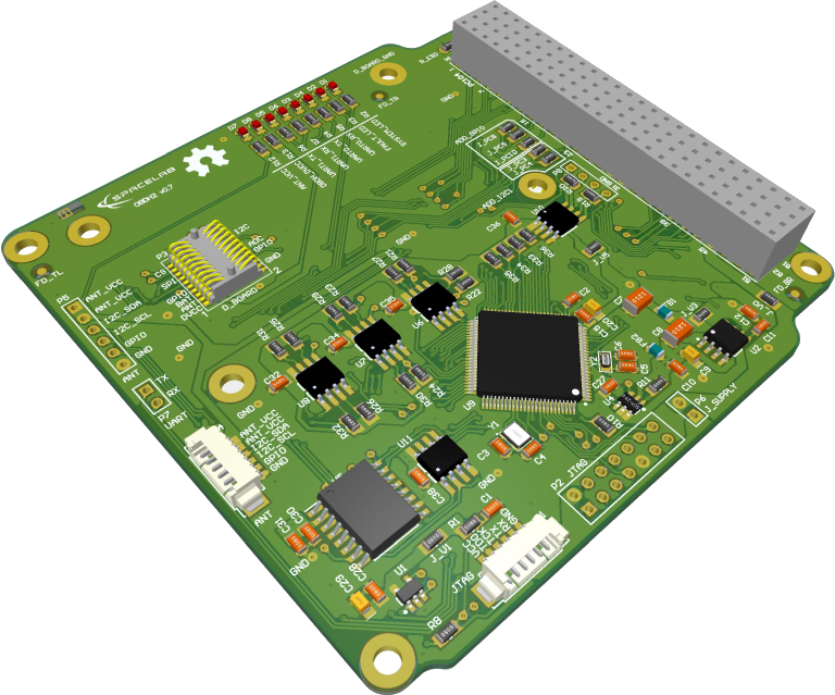
Fig. 23 OBDH module.
More information about this module can be found in [10].
Telemetry, Tracking and Command Module
The TTC (Telemetry, Tracking and Command Module) (or TT&C) is responsible for making the communication between the Earth (a ground station) and the satellite and is divided into two sub-modules: Beacon and downlink/uplink. The beacon is an independent sub-module that transmits a periodic signal containing satellite identification data (ID) and some basic telemetry data. The downlink/uplink sub-module is the primary communication device. It has a bidirectional data link to receive telecommands from the Earth and transmit all available data back to Earth. The module board can be seen in Fig. 24.
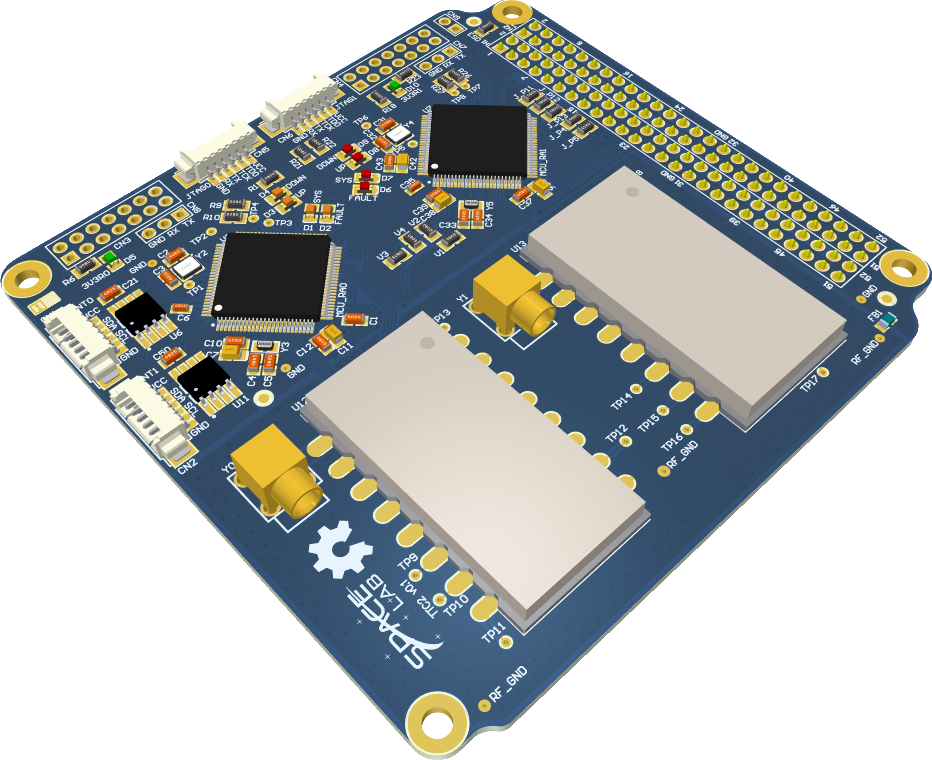
Fig. 24 TTC module.
More information about this module can be found in [21].
Antenna Module
The used antenna module is the CubeSat deployable VHF and UHF antenna from ISISpace [9]. It is a four monopole antenna built with tape strings (up to 55 cm) and compliant with the CubeSat standard (dipole or turnstile options are also available). The deployment method is the burning wire, which can be controlled digitally through a I²C interface. To allow redundancy, two independent deployment controllers can be activated separately. Also, the construction of this module allows the installation of a solar panel at the top side. The RF gain is about 0 dBi.
A picture of the antenna module (with all antennas released) can be seen in Fig. 25.
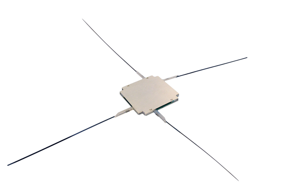
Fig. 25 Antenna module from ISISpace.
The chosen configuration for this mission can be seen below (using Fig. 26 as reference):
Configuration: 2 monopoles (UHF) + 1 dipole (VHF)
Antenna 1: UHF - 450 MHz (downlink/uplink)
Antenna 2: UHF - 401.635 MHz (both EDCs)
Antenna 3 and 4: VHF - 145.97 MHz (beacon)
Tuning structure size: 2U
Mounting position: Top
Supply voltage: 3.3 V
I²C control type: Dual bus
Primary I²C address: 31h (7-bit address)
Redundant I²C address: 32h (7-bit address)
I²C watchdog: Enabled with a time out of 60 seconds.
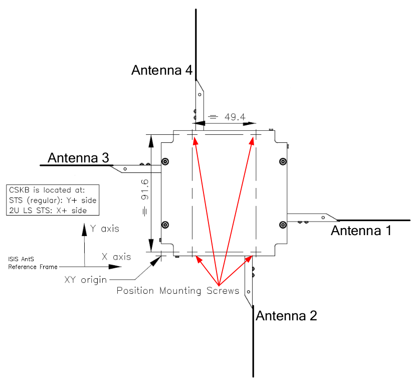
Fig. 26 Configuration reference of the antenna module.
A temperature sensor and the state of four deployment switches (1 per monopole) are also available in the digital interface. These switches indicate if a monopole is released or not, and can be used as feedback of the deployment process.
RF Splitter
As the satellite has two EDCs (in a cold redundancy scheme) and just one dedicated antenna (antenna 2, UHF monopole), a RF splitter is also being used. This way, the received signal from a single monopole can be processed by both EDCs. The used model is the Z99SC-62-S+ from Mini-Circuits [2]. A picture of this device is available in Fig. 27.
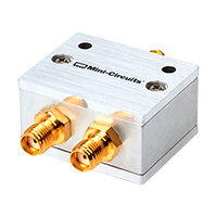
Fig. 27 Mini-Circuits Z99SC-62-S+ RF splitter.
To mechanically install the Z99SC-62-S+ device in the satellite, a board in the PC-104 form factor is being used, as can be seen in Fig. 28. More information about the RF splitter module is available in [18].
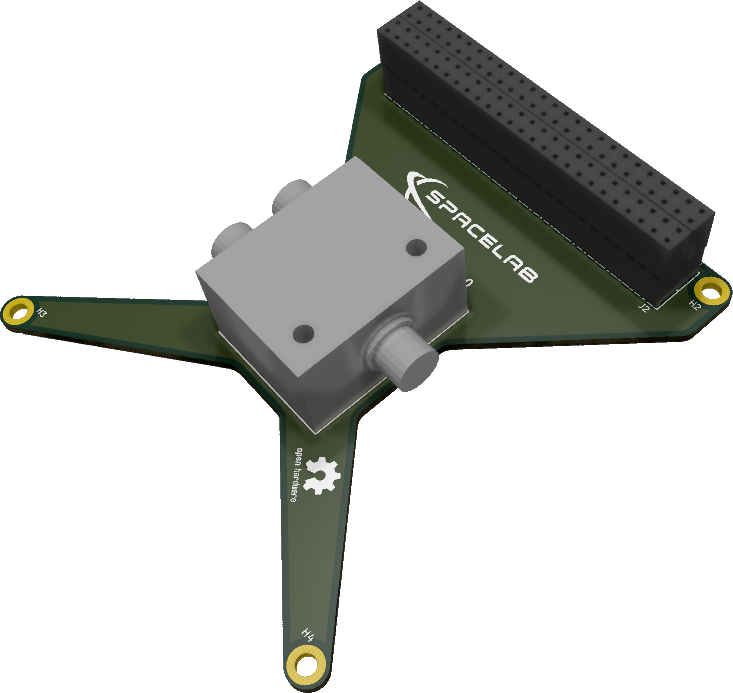
Fig. 28 RF splitter module.
Electrical Power System
The EPS (Electrical Power System) is the module designed to harvest, store and distribute energy for the satellite. The energy harvesting system is based on solar energy conversion through the solar panels attached to the CubeSat structure. The EPS is designed to operate the solar panels at their maximum power point (MPPT (Maximum Power Point Tracking)). The board also measures the solar panels current, voltage and temperature of the batteries. The harvested solar energy is stored in a battery module connected to the EPS. Several integrated buck DC-DC converters do the energy distribution. The full EPS system is composed of the solar panels, the EPS PCB (Printed Circuit Board) and the battery module. A general view of the EPS board can be seen in Fig. 29.
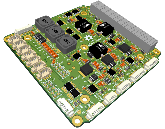
Fig. 29 EPS module.
The module is a direct upgrade from the EPS of FloripaSat-1 [8], which grants a flight heritage rating. The improvements focus on providing a cleaner and more generic implementation compared to the previous version, more reliability in software, and adaptations for the new mission requirements.
More information about this module can be found in [14].
Battery Module
The used battery module is the “Battery Module 4C”, which is a separate battery module from the EPS board and composed by four lithium-ion 18650 cells. Besides the cells, the board has connectors for interfacing signals and power lines with the EPS module, 2 power resistors to operate as heaters to maintain the cell’s temperature during eclipse periods, and 4 temperature sensors. The batteries used are the ICR18650-30B lithium-ion cells from Samsung [6], which are connected in series and parallel (two sets of two parallel cells in series) to supply the required voltage and current. Each cell is fixed with 18650 metal holders, and between the pairs, the power resistor is attached with a thermal element in the middle. A mechanical mount is placed over the batteries and screwed to the board, providing better stress resistance. Also, PC-104 through-hole pads are present on the board for a connector that could be used for mechanical integration with the EPS, or, with future improvements, an interface for power, data or control signals. The board is a direct improvement from the first battery board used in the FloripaSat-1 mission [8].
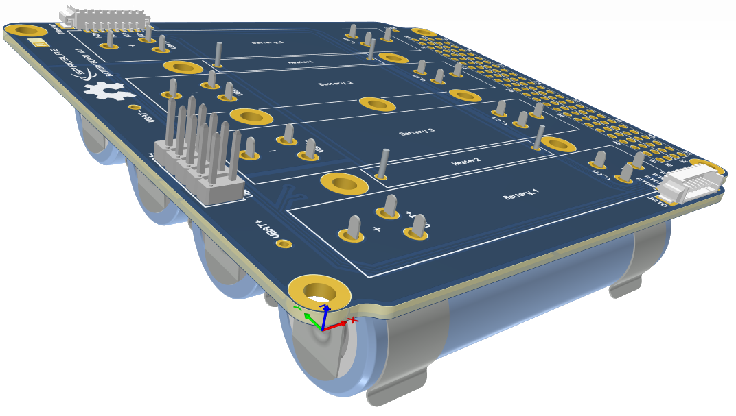
Fig. 30 Battery module board.
More information about the battery module can be found in [12].
Solar Panels
The solar panels are a set of 5 custom-made panels manufactured by ORBITAL, a Brazilian company, and a single panel from ISISpace. The panels feature protection diodes and high-efficiency solar cells, which are the CESI’s CTJ-30 [22] with dimensions 6.9 × 3.9 cm (area 26.5 cm²). This cell is qualified for space use by ESA with an efficiency of 29.5 % (AM0, BOL). The panels do not include magnetometers, sensors, and other devices. The top solar panel is a model from ISISpace to ensure mechanical compatibility with the antenna module (also from ISISpace). These two types of solar panels can be seen in Figures Fig. 31 and Fig. 32.
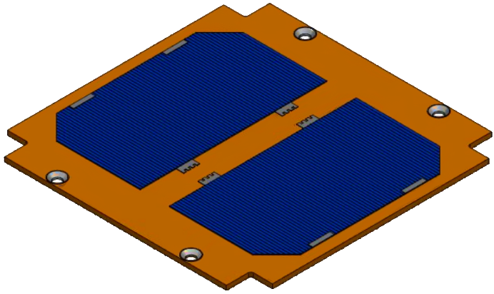
Fig. 31 Conceptual solar panel from ORBITAL.
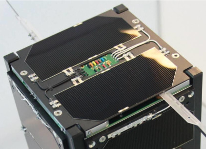
Fig. 32 Top solar panel from ISISpace.
Kill-Switches and RBF
Two electronic switches have been implemented into the design to allow for the (redundant) deployment detection of the CubeSat when deployed from the POD. This electronic micro switch can be used to prevent the satellite from starting up during launch, as is required for all CubeSat launches and hence acts as a Kill-Switch. The Kill-Switch is the Panasonic AV4 microswitch (AV402461), as seen in Fig. 33.
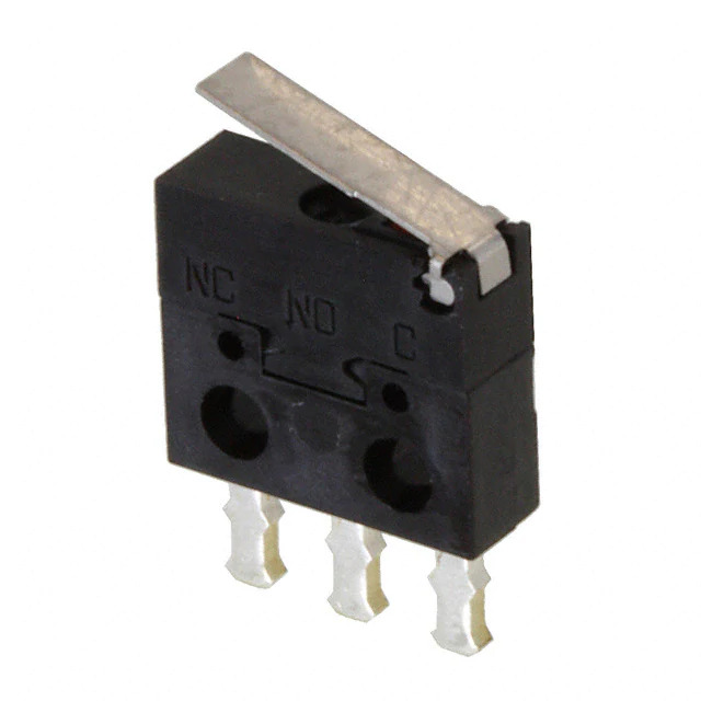
Fig. 33 Panasonic AV402461 Microswitch.
The Kill-Switch mechanism in the mechanical structure has combined the function of providing deployment and detection (Fig. 34). The travel of the actual switch of the Kill-Switch itself is so short that the Kill-Switch could “detect deployment” of the CubeSat from the launch adapter simply due to launch vibrations. To overcome this issue the Kill-Switch has been rotated so that there is a positive obstruction in front of the switch which needs 8 mm of deployment before deployment can be detected with the Kill-Switch. In Fig. 34 the Kill-Switch parts are highlighted, and the stowed and deployed configuration is shown.
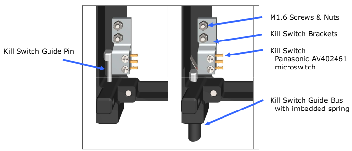
Fig. 34 Kill-Switches installed in the mechanical structure.
The contact arrangement of the microswitch and the current rating are detailed in Fig. 35 and Table 18.
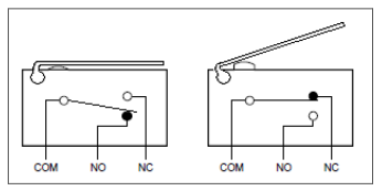
Fig. 35 The contact arrangement of the microswitch.
Characteristic |
Minimum |
Typical |
Maximum |
Unit |
|---|---|---|---|---|
Switch Current |
2 |
50 |
100 |
mA |
DC Voltage across switch contacts |
n/a |
n/a |
30 |
V |
Contact resistance microswitch |
n/a |
n/a |
200 |
\(\mathrm{m}\Omega\) |
Attitude Control System
The Attitude Control System (ACS (Attitude Control System)) is a passive attitude control system, which depends on the Earth’s magnetic field to rotate and stabilize the satellite [35, 39]. The system is composed of one permanent magnet to create a force to align the magnet with the Earth’s magnetic field and four hysteresis bars to dampen the cube oscillations and achieve stabilization.
When equilibrium is achieved, the permanent magnet aligns with the Earth’s field lines. The hysteresis bars convert oscillation and rotation energy into heat, maintaining the alignment through the magnetic moment. The components are placed in positions to minimize the magnet’s interaction with the hysteresis bars, which limits the magnetic moment of the magnet [34]. Fig. 36 shows the mounting of the hysteresis bars (green) and the permanent magnet (red) on the mechanical structure. The whole passive ACS was implemented according to [34].
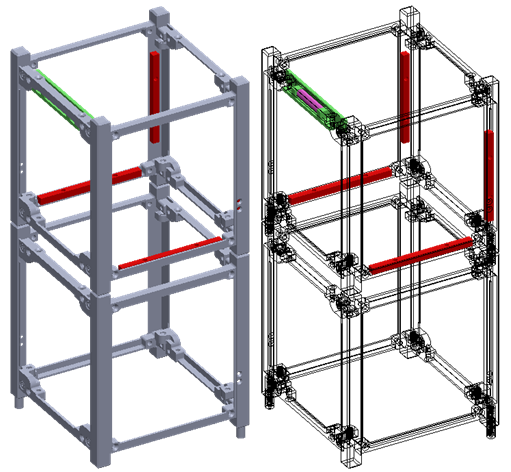
Fig. 36 ACS subsytem. Rare earth magnet (pink) and hysteresis bars (red) installed in the structure.
As a passive magnetic attitude control system is used, it is possible to stabilize only one axis. So, the CubeSat will still slowly (due to hysteresis bars) rotate around this axis, even after stabilized. A N45 neodymium magnet and 4 hysteresis bars of Permanorm 5000 H2 are used (courtesy of Vacuumschmelze GmbH & Co. KG). The hysteresis bar’s material is shaped to maximize stabilization, which is the most critical part of attitude control.
Many conditions impact the detumbling time, which is the time required for the satellite to stabilize. Magnetic passive attitude stabilization systems such as the one developed for this mission achieve the equilibrium state within a few weeks of operation [39].
The GOLDS-UFSC satellite does not feature an orbit control subsystem.
Thermal control
An active control gives the thermal control: two resistors (24 \(\Omega\)) to protect the batteries against low temperatures and two RTDs to monitor the temperature. The control is an ON/OFF control.
Mechanical Structure
The USIPED 2-Unit CubeSat structure is developed as a generic, modular satellite structure based on the CubeSat standard. The modular chassis allows up to two 1-Unit stack of PCBs, or other modules, to be mounted inside the chassis, using the PC-104 standard and spacers attached to the structure. In addition, there are 4 slots in the middle section, providing space for the interface boards and the ACS. The solar panels and antennas are externally mounted, providing a complete mechanical solution. A picture of this structure can be seen in Fig. 37.
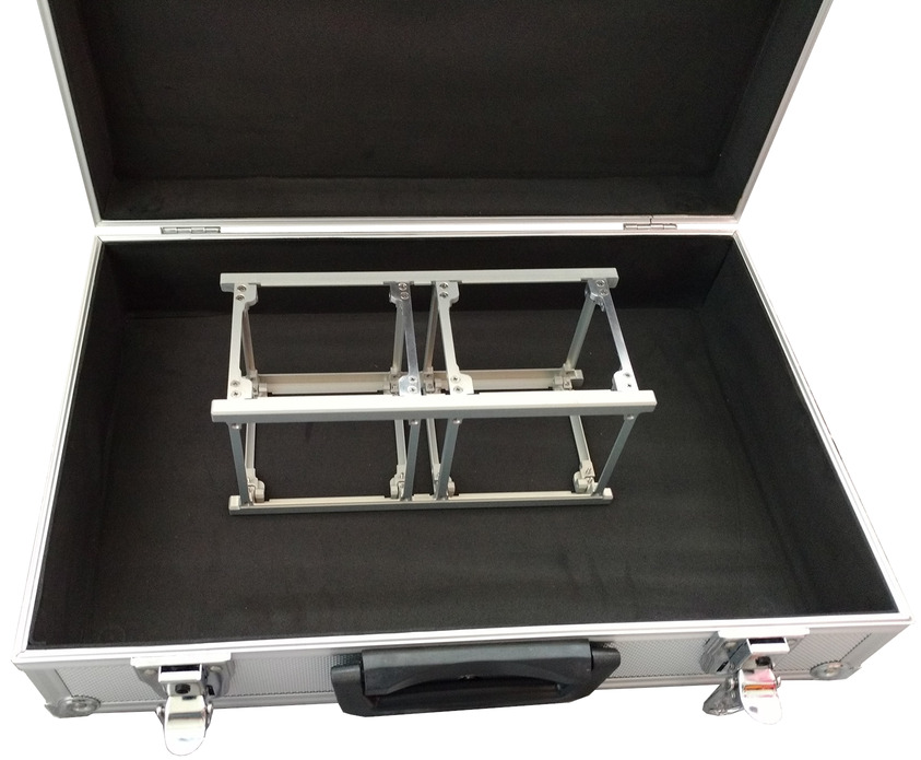
Fig. 37 2U CubeSat structure from Usiped.
The structure will support the loads and vibration along the entire life cycle of the satellite, which includes every phase prior to the launch, the launch itself, and the operation of the CubeSat in space. In addition, the structure must keep all the parts of the CubeSat fastened at the proper position during the launch and operation, provide a conductive thermal path for heat transfer, and provide access for assembly, integration, and verification.
The material of all its parts is aluminum T6065, except for the bolts and thread. This material presents good mechanical properties for space application, such as weight, strength, fracture and fatigue resistance, thermal expansion, and ease of manufacturing. The surfaces of the CubeSat in contact with the deployer are anodized and grounded for proper and smooth ejection. The main views of the assembled structure is presented in Fig. 38, as well as its main dimensions.
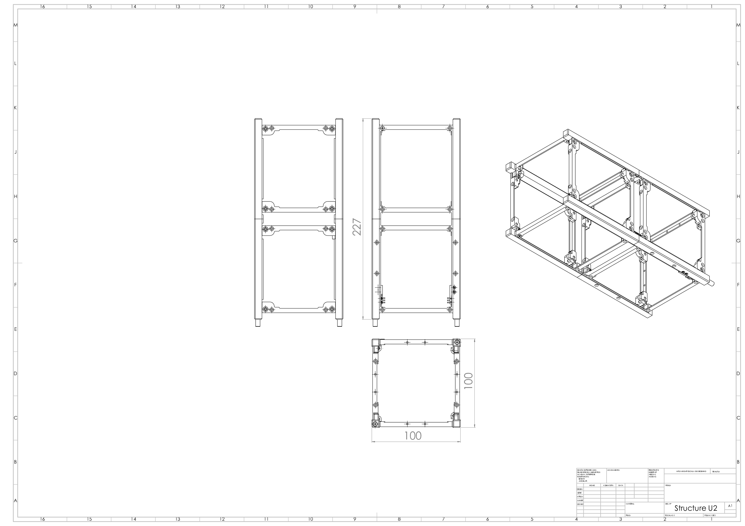
Fig. 38 Views and main dimension of the structure.
Interconnection Modules
PC-104 Interconnection Boards
The PC-104 interconnection boards are intended to be used as an interconnection of the two PC-104 bus segments of the 2U structure (top and bottom units). This interconnection is made with a set of PicoBlade cables between the top and bottom boards. The set of two boards can be seen in Fig. 39.
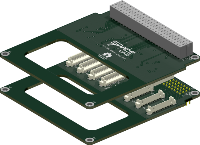
Fig. 39 PC-104 adapter boards (top and bottom).
More information about these boards can be found in [17].
External Connection Boards
The Interstage Interface Panels (IIP) are three vertical internally mounted PCBs designed to give external access to up to four modules inside of a 2U CubeSat during final assembly, integration, and testing (AIT) before launch. The complete set of boards allows the nanosatellite to be charged, programmed, and debugged. The usage of this hardware platform takes into account the use of a MSP-FET: MSP430 Flash Emulation Tool from Texas Instruments for JTAG programming and debugging, UART debugging through a mini USB type B port interfacing the FT4232H USB bridge IC from FTDI, a JST XH header for charging internal batteries and a Remove Before Flight (RBF) pin header. The boards can be seen in Fig. 40.
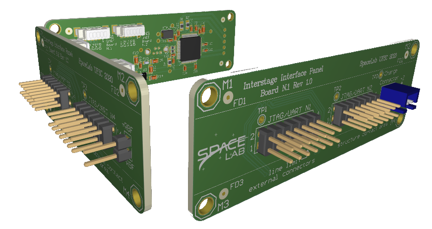
Fig. 40 Set of external connection boards.
For this mission, the four JTAG connectors are being used as described in Table 19.
JTAG Connector |
Connected Module |
|---|---|
JTAG/UART N1 |
OBDH |
JTAG/UART N2 |
EPS |
JTAG/UART N3 |
TTC |
JTAG/UART N4 |
None |
More information about these boards can be found in [13].
Payloads
The GOLDS-UFSC satellite is planned to carry the “EDC” as the primary and main payload. Moreover, in order to asses the radiation levels present in the satellite, an additional scientific experiment is planned in the form of a Radiation instrument. Each one of these payloads are presented next.
Environmental Data Collection
The Environmental Data Collector (EDC (Environmental Data Collection)) is a CubeSat-compatible payload that decodes signals from Platform Transmitter Terminals (PTTs) belonging to the Brazilian Environmental Data Collection System (SBCD (Sistema Brasileiro de Coleta de Dados)) and the Argos-2 System. It is the main payload of the GOLDS-UFSC mission.
The main features of this payload are listed below, a 3D model of the EDC board can be seen in Fig. 41.
Reception/decoding of SBCD and Argos-2 signals on the 401.635 MHz ± 30 kHz frequency range.
Can decode up to 12 PTT signals simultaneously.
Attaches a header to decoded messages with frequency, time, and signal strength information.
Full speed I²C interface (400 kbit/s) for the OBC communication.
Full-duplex RS-485 interface with fail-safe for the OBC communication.
5 V power supply.
Memory capable of storing up to 64 decoded user messages.
Generates housekeeping information, including current supply, board temperature, digitized signal RMS level, front-end PLL synchronism state, and overcurrent events.
Can capture a 2048 sample sequence (16 ms window) from the received signal upon request.
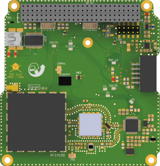
Fig. 41 EDC board.
Two identical EDC boards will be used in a cold redundancy configuration for this mission. More information about this payload can be found in [7].
Radiation instrument
The Radiation instrument is a radiation-hardened reconfigurable hardware platform designed for a radioactive environment, having as the main feature the possibility to change the hardware configuration of the FPGA (Field-Programmable Gate Array) through remote uplink of its bitstream.
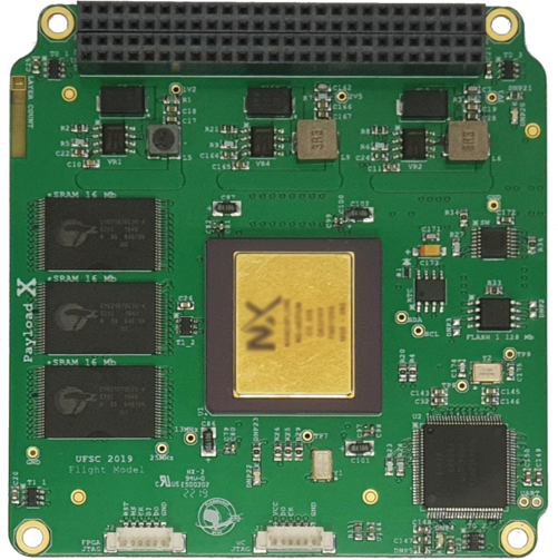
Fig. 42 Radiation instrument board.
More information about this payload can be found in [38].