Service Module Overview
This section presents the design description of GOLDS-UFSC.
General Diagrams
The CubeSat’s subsystems are positioned in the 2U physical structure as exemplified in Fig. 11.
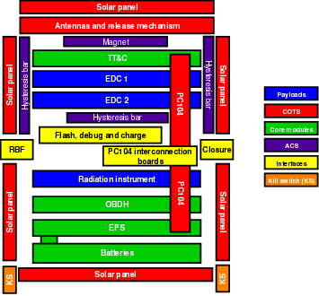
Fig. 11 Subsystems positioning.
Power Diagram
In Fig. 12 is presented a block diagram showing the satellite’s power buses. The EPS module distributes these buses and has the ability to turn on and off some subsystems, while other modules also have direct control over some dc regulators [14]. The bus used for the antenna module is only active during its deployment. The current values shown are the maximum capability and not the nominal operating values; these are determined by the variable power generation of the solar panels as well as the loads present at a given time of the satellite’s operation.
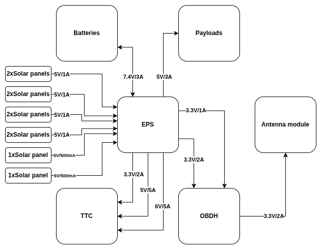
Fig. 12 Power diagram.
Data Path Diagram
The data path diagram is shown in Fig. 13.
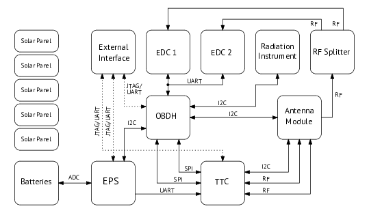
Fig. 13 Data path diagram.
Deployment Sequence
The deployment sequence of the satellite is the routine to be executed just after the launch. The main objective of this operation is to deploy the antennas and prepare the satellite to start its normal operation.
After the satellite is ejected from the deployer, the kill switches enable the electric power and the three core modules to execute the boot sequence (EPS, OBDH and TTC). The EPS module is ready to operate when the boot finishes. The OBDH and the TTC modules waits for a determined period before starting the normal execution.
As the OBDH and the TTC have access to the antenna module, both subsystems can control the deployment of the antennas. Following the CDS (CubeSat Design Specification) specifications [40], all CubeSats must wait 30 minutes to deploy the antennas and 45 minutes to transmit any RF signal. This way, the OBDH waits 45 minutes to send the deployment command to the antenna module. As redundancy, the TTC waits 55 minutes to execute the same operation.
The Fig. 14 has a flowchart that illustrates the deployment sequence of the service modules.
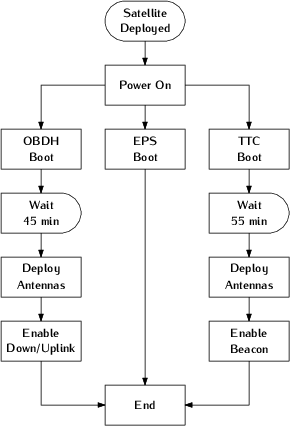
Fig. 14 Flowchart of the deployment sequence.
Beacon Operation
After the beacon microcontroller’s boot sequence, the beacon’s operation starts. The normal operation consists of reading the data from the EPS and the TTC modules, transmitting the valid data (EPS or TTC package, in this order of priority), waiting 60 seconds, and repeating this sequence. The Fig. 15 has a flowchart of this behavior.
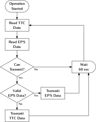
Fig. 15 Flowchart of the normal beacon operation.
OBDH Operation
After the boot sequence of the OBDH microcontroller, the operation of the OBDH starts. The regular operation consists of reading the housekeeping data from the EPS, TTC, payloads, antenna module, and the OBDH (its own housekeeping data), saving the read data on the non-volatile memory, and transmitting the housekeeping data of the satellite as a beacon. After that, it waits 60 seconds and checks if a new telecommand was received; if true, it processes the telecommand; if not, it does nothing. After this sequence, these steps start again. The Fig. 16 has a flowchart of this behavior.
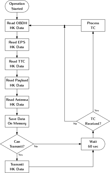
Fig. 16 Flowchart of the normal OBDH operation.
Telecommand Processing
Figure Fig. 17 shows the telecommand processing flow.
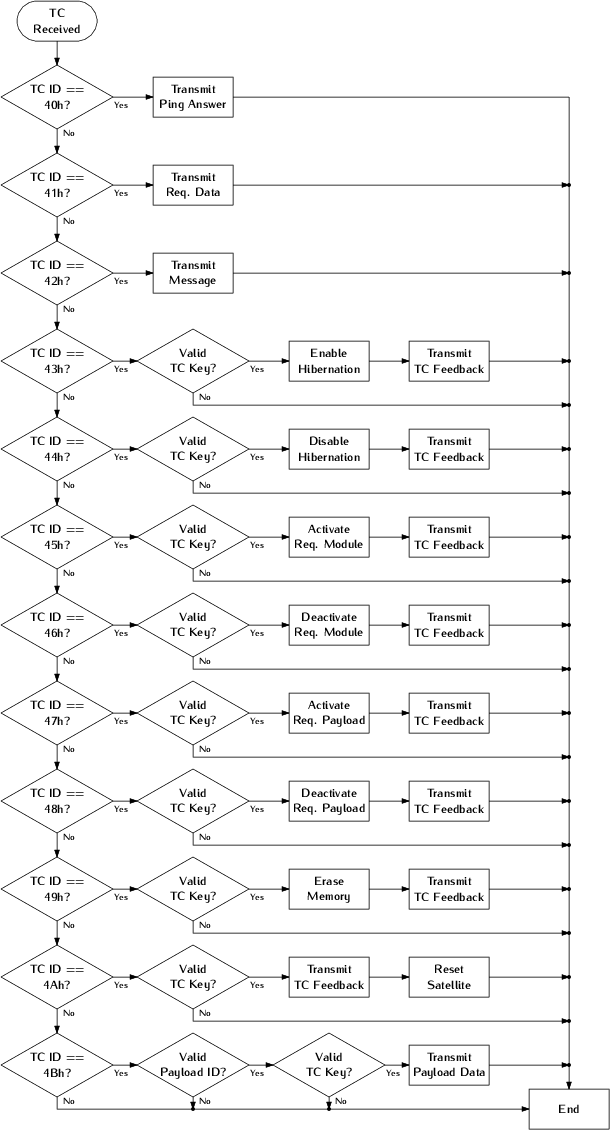
Fig. 17 Flowchart of telecommand processing.
EPS Operation
The operation of the EPS microcontroller starts shortly after the release of the CubeSat in its orbit by the deployer. In the first 60 minutes, the module operation consists of reading the housekeeping data from its sensors and managing the duty cycles of the MPPT and heaters. When operational, the TTC and OBDH modules send separate periodic requests to the EPS for forwarding, the housekeeping data acquired. The TTC receives a simplified version, while the OBDH receives a complete version of the data. The Fig. 18 has a flowchart of this behavior.
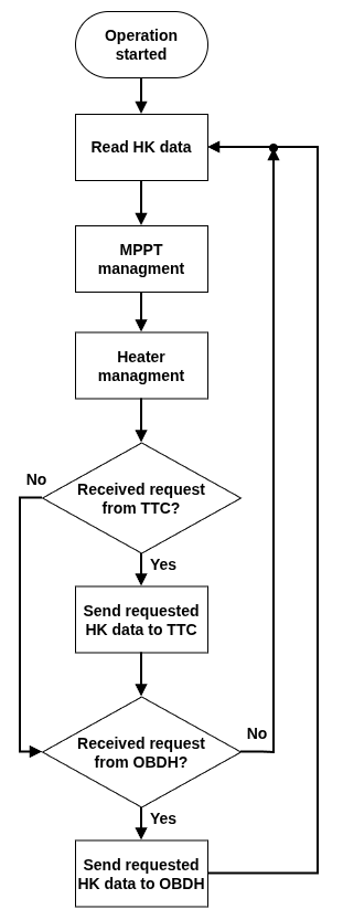
Fig. 18 Flowchart of the normal EPS operation.
Interface Data Sheet (IDS)
Interface
To electrically connect all the satellite modules, a PC-104 bus standard is being used. This bus is composed by 104 lines disposed by four rows of 26 pins each (with a vertical and horizontal pitch of 2,54 mm).
Using the Fig. 19 as reference, all used positions and signals of the PC-104 bus are presented in Table 14. The Table 15 describes each signal and which modules are connected to them.
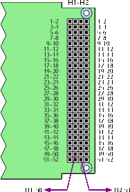
Fig. 19 Reference diagram of the PC-104 bus (top view of a generic module).
Pin Row |
H1 Odd |
H1 Even |
H2 Odd |
H2 Even |
|---|---|---|---|---|
1-2 |
||||
3-4 |
EDC_1_EN |
EDC_2_EN |
||
5-6 |
BE_UART_RX |
|||
7-8 |
RA_GPIO_0 |
RA_GPIO_1 |
BE_UART_TX |
GPIO_0 |
9-10 |
RA_GPIO_2 |
BE_EN |
||
11-12 |
RA_RESET |
RA_EN |
BE_SPI_MOSI |
BE_SPI_CLK |
13-14 |
BE_SPI_CS |
BE_SPI_MISO |
||
15-16 |
||||
17-18 |
EDC_UART_RX/TX |
PLX_EN |
GPIO_1 |
|
19-20 |
EDC_UART_TX/RX |
GPIO_2 |
GPIO_3 |
|
21-22 |
GPIO_4 |
|||
23-24 |
||||
25-26 |
PL_VCC |
PL_VCC |
||
27-28 |
TTC_VCC |
TTC_VCC |
||
29-30 |
GND |
GND |
GND |
GND |
31-32 |
GND |
GND |
GND |
GND |
33-34 |
||||
35-36 |
RA_SPI_CLK |
ANT_VCC |
ANT_VCC |
|
37-38 |
RA_SPI_MISO |
|||
39-40 |
RA_SPI_MOSI |
RA_SPI_CS |
||
41-42 |
PL_I2C_SDA |
GPIO_5 |
||
43-44 |
PL_I2C_SCL |
|||
45-46 |
OBDH_VCC |
OBDH_VCC |
BAT_VCC |
BAT_VCC |
47-48 |
PL_VCC |
PL_VCC |
||
49-50 |
RA_VCC |
RA_VCC |
EPS_I2C_SDA |
|
51-52 |
BE_VCC |
BE_VCC |
EPS_I2C_SCL |
Signal |
Pin(s) |
Used By |
Description |
|---|---|---|---|
GND |
H1-29/30/31/32, H2-29/30/31/32 |
All |
Ground reference |
BAT_VCC |
H2-45, H2-46 |
EPS |
Battery terminals (+) |
ANT_VCC |
H2-35, H2-36 |
EPS, ANT |
Antenna power supply (3.3 V) |
OBDH_VCC |
H1-45, H1-46 |
EPS, OBDH |
OBDH power supply (3.3 V) |
TTC_VCC |
H2-27, H2-28 |
EPS, TTC |
TTC power supply (3.3 V) |
PL_VCC |
H1-47/48, H2-25/26 |
EPS, EDC 1/2, Radiation instrument |
Payloads power supply (5 V) |
RA_VCC |
H1-49, H1-50 |
EPS, TTC |
Main radio power supply (5 V) |
BE_VCC |
H1-51, H1-52 |
EPS, TTC |
Beacon power supply (6 V) |
RA_SPI_CLK |
H1-35 |
OBDH, TTC |
CLK signal of the main radio SPI bus |
RA_SPI_MISO |
H1-37 |
OBDH, TTC |
MISO signal of the main radio SPI bus |
RA_SPI_MOSI |
H1-39 |
OBDH, TTC |
MOS signal of the main radio SPI bus |
RA_SPI_CS |
H1-40 |
OBDH, TTC |
CS signal of the main radio SPI bus |
EPS_I2C_SDA |
H2-49 |
OBDH, EPS |
SDA signal of the EPS I2C bus |
EPS_I2C_SCL |
H2-51 |
OBDH, EPS |
SCL signal of the EPS I2C bus |
BE_UART_RX |
H2-5 |
EPS, TTC |
EPS TX, Beacon RX (UART bus) |
BE_UART_TX |
H2-7 |
EPS, TTC |
EPS RX, Beacon TX (UART bus) |
EDC_UART_TX/RX |
H1-25 |
OBDH, EDC 1/2 |
OBDH TX, EDCs RX (UART bus) |
EDC_UART_RX/TX |
H1-27 |
OBDH, EDC 1/2 |
OBDH RX, EDCs TX (UART bus) |
BE_EN |
H1-10 |
EPS, TTC |
Beacon radio power enable |
RA_EN |
H1-12 |
EPS, OBDH |
Main radio power enable |
EDC_1_EN |
H2-3 |
OBDH, EDC 1 |
EDC 1 enable signal |
EDC_2_EN |
H2-4 |
OBDH, EDC 2 |
EDC 2 enable signal |
PLX_EN |
H1-18 |
OBDH, Radiation instrument |
Radiation instrument enable (GPIO) |
PL_I2C_SDA |
H1-41 |
OBDH, Radiation instrument |
SDA signal of the payload I2C bus |
PL_I2C_SCL |
H1-43 |
OBDH, Radiation instrument |
SCL signal of the payload I2C bus |
GPIO_N |
H1-20, H2-8/18/20/22/42 |
OBDH |
GPIO pin (not used) |
This project’s distribution pattern of pins is a mix of multiple patterns from CubeSat module manufacturers, like GomSpace, ISIS, and Endurosat. Some pins are positioned to meet specific project requirements, and the adopted pattern may only be partially compatible with some commercial modules.
Beyond the PC-104 bus, some signals are connected directly by wires and cables, like the control and power pins of the antenna module, the battery charger, and the programming ports.
Form Factor
The form factor follows a similar specification of the PC-104 standard [5]. The connector used for the interface differs given the module; the isolation height and presence of a pin or receptacle are defined from the overall stack up of the subsystems inside the CubeSat 2U structure.
The core modules have smoothed edges, and some linear mounting hole distances are different from the standard; these are according to fit in a CubeSat form factor. The PC-104 form factor used can be seen in Fig. 20.
Fig. 20 PC-104 Form Factor.
Telecommunication
This section describes the configuration and behavior of the telecommunication subsystems of the satellite. There are three types of links available in the CubeSat: beacon, downlink, and uplink. The beacon link is a periodic transmission of packets with basic telemetry data of the satellite (containing data from the EPS or TTC subsystems). The downlink is the link used to receive all data from the satellite, including the results of all experiments, telemetry data, and telecommands feedback. Moreover, the uplink sends telecommands from a ground station to the satellite.
The payload of all packets follows the same structure, with an ID number, the source address (callsign), and the packet’s content (variable according to each type of packet). Following the NGHam protocol characteristics, the maximum packet length, including the ID and the source address, is 220 bytes. The Fig. 21 illustrates this packet structure.
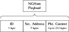
Fig. 21 Payload structure of the GOLDS-UFSC packets.
The Table 16 summarizes all types of packets transmitted or received by satellite, with the ID number, structure and length, and access type of each packet.
Link |
Packet Name |
Payload ID |
Source Callsign |
Data (up to 212 bytes) |
Size (bytes) |
Access |
|---|---|---|---|---|---|---|
Downlink (VHF) |
EPS data |
00h |
“ ” + “PY0EFS” |
EPS data |
46 |
Public |
Downlink (VHF) |
Message broadcast |
01h |
“ ” + “PY0EFS” |
Requester + dst. callsign + message |
22 to 60 |
Public |
Downlink (VHF) |
Ping answer |
02h |
“ ” + “PY0EFS” |
Requester callsign |
15 |
Public |
Downlink (UHF) |
General telemetry |
10h |
“ ” + “PY0EFS” |
OBDH/EPS data |
78 |
Public |
Downlink (UHF) |
Data request answer |
11h |
“ ” + “PY0EFS” |
Requester callsign + data ID + ts. + data |
20 to 220 |
Public |
Downlink (UHF) |
Payload data |
12h |
“ ” + “PY0EFS” |
Payload ID + payload data |
9 to 220 |
Public |
Downlink (UHF) |
TC feedback |
13h |
“ ” + “PY0EFS” |
Req. callsign + TC packet ID + timestamp |
20 |
Public |
Downlink (UHF) |
Parameter value |
14h |
“ ” + “PY0EFS” |
Req. callsign + Sub. ID + Param. ID + Param. Val. |
21 |
Public |
Downlink (UHF) |
Packet broadcast |
15h |
“ ” + “PY0EFS” |
Data of “Transmit packet” TC |
8 to 60 |
Public |
Uplink |
Ping request |
40h |
Any Callsign |
None |
8 |
Public |
Uplink |
Data request |
41h |
Any Callsign |
Data ID + Start ts. + End ts. + Hash |
37 |
Private |
Uplink |
Broadcast Message |
42h |
Any Callsign |
Dst. callsign + message |
15 to 53 |
Public |
Uplink |
Enter hibernation |
43h |
Any Callsign |
Hibernation in hours + Hash |
30 |
Private |
Uplink |
Leave hibernation |
44h |
Any Callsign |
Hash |
28 |
Private |
Uplink |
Activate module |
45h |
Any Callsign |
Module ID + Hash |
29 |
Private |
Uplink |
Deactivate module |
46h |
Any Callsign |
Module ID + Hash |
29 |
Private |
Uplink |
Activate payload |
47h |
Any Callsign |
Payload ID + Hash |
29 |
Private |
Uplink |
Deactivate payload |
48h |
Any Callsign |
Payload ID + Hash |
29 |
Private |
Uplink |
Erase memory |
49h |
Any Callsign |
Hash |
28 |
Private |
Uplink |
Force reset |
4Ah |
Any Callsign |
Hash |
28 |
Private |
Uplink |
Get payload data |
4Bh |
Any Callsign |
Payload ID + Args. + Hash |
41 |
Private |
Uplink |
Set parameter |
4Ch |
Any Callsign |
Subsystem ID + Param. ID + Param. value + Hash |
34 |
Private |
Uplink |
Get parameter |
4Dh |
Any Callsign |
Subsystem ID + Parameter ID + Hash |
30 |
Private |
Uplink |
Transmit packet |
4Eh |
Any Callsign |
Any sequence of bytes + Hash |
8 to 60 |
Private |
Uplink |
Update TLE |
4Fh |
Any Callsign |
Line + TLE line + Hash |
98 |
Private |
The ID of the subsystems, modules, and payloads are available in Table 17.
Type |
ID Number |
Description |
|---|---|---|
Subsystem |
0 |
OBDH |
Subsystem |
1 |
TTC 1 |
Subsystem |
2 |
TTC 2 |
Subsystem |
3 |
EPS |
Module |
1 |
Battery heater |
Module |
2 |
Beacon |
Module |
3 |
Periodic telemetry |
Payload |
1 |
EDC 1 |
Payload |
2 |
EDC 2 |
Payload |
3 |
Radiation instrument |
Authentication
All the telecommands classified as private use an HMAC (Hash-based Message Authenticaion Code) authentication scheme. Every type of private telecommand has a unique 16-digit ASCII character key that with the telecommand sequence (or message) generates an 160-bits (20-bytes) hash sequence to be transmitted together with the packet payload. The used hash algorithm is the SHA-1 (Secure Hash Algorithm 1). The Fig. 22 illustrates this authentication method.
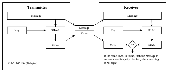
Fig. 22 Diagram of the used HMAC scheme.
Operation Licenses
Regarding the non-amateur radios frequencies, Resolution 685, of October 9, 2017 from ANATEL establishes that:
Art. 9. Assign to the Private Limited Service (SLP), for use by systems for capturing and transmitting scientific data related to space operation, on a secondary basis, the following sub-ranges (related to this project):
400.15 MHz to 401 MHz;
449.75 MHz to 450.25 MHz.
Art. 17. The allocation of all radio frequency bands dealt with in this Resolution follows the restrictions imposed by the respective allocation.
Single paragraph. Those interested in the use of the radio frequency bands object of this Resolution must provide in their projects, until specific regulations are issued on the conditions of use of these bands, criteria for harmonious coexistence with the existing systems in these bands, maintaining specific coordination, when necessary, of such so that incoming systems do not cause harmful interference to existing systems.
Thus, a process must be carried out for radio 1 (146 MHz) in the amateur radio band, and another process for the radios with 401 MHz and 450 MHz. Since the last two radios must be a secondary service SLP where a preliminary study is necessary on the harmonic coexistence with the existing systems in these bands.